BUBBLE NEST
HOTEL CONSERVATORY STRUCTURES IN NORTH LONDON
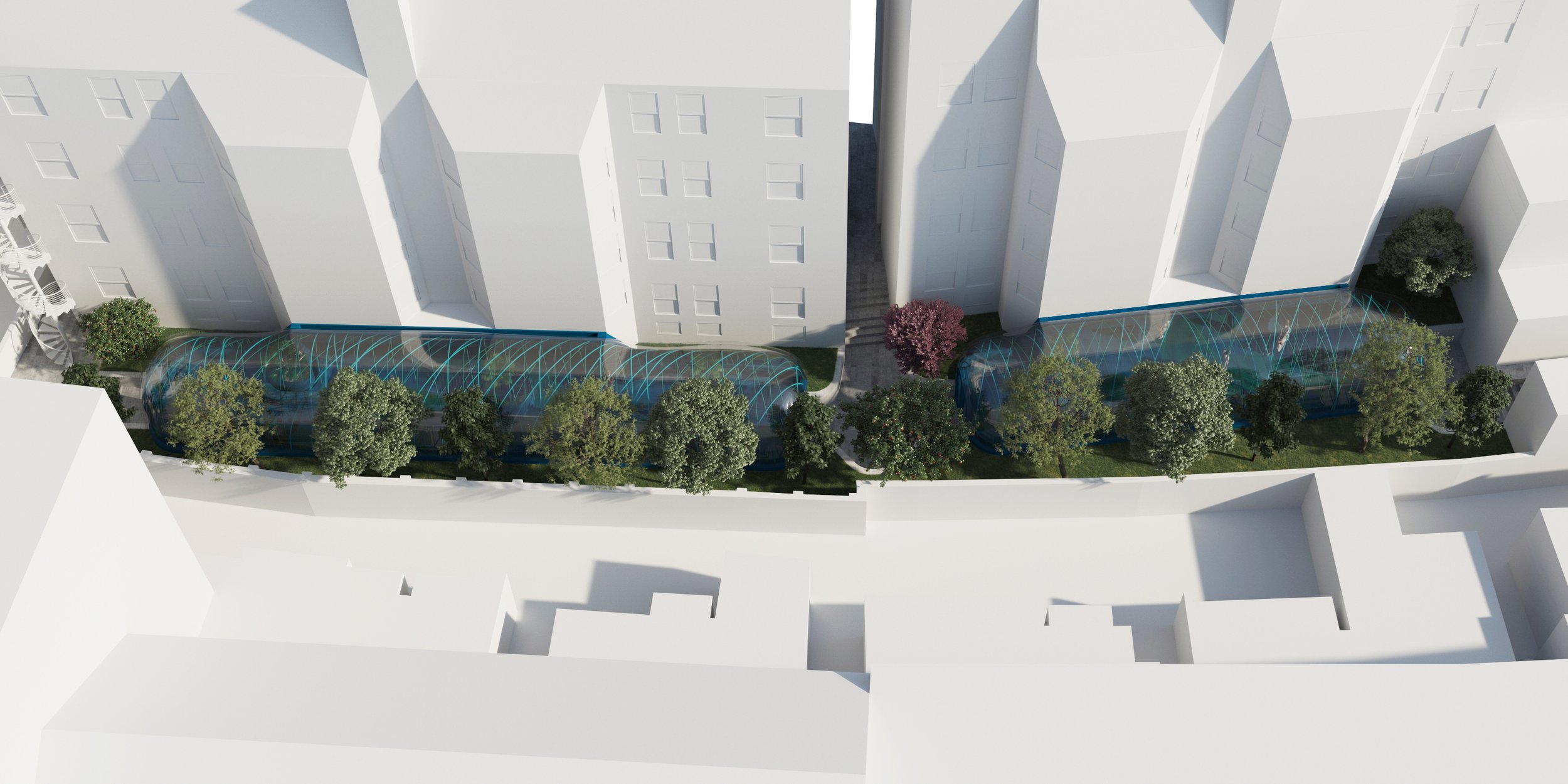
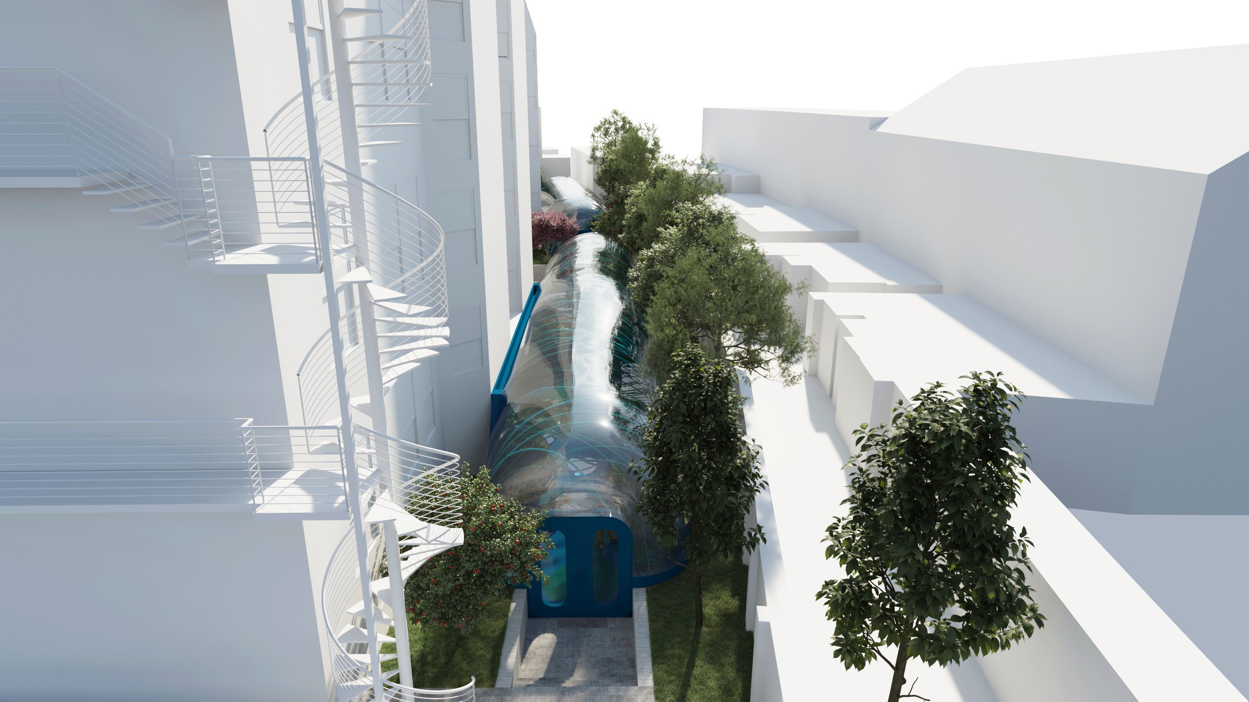
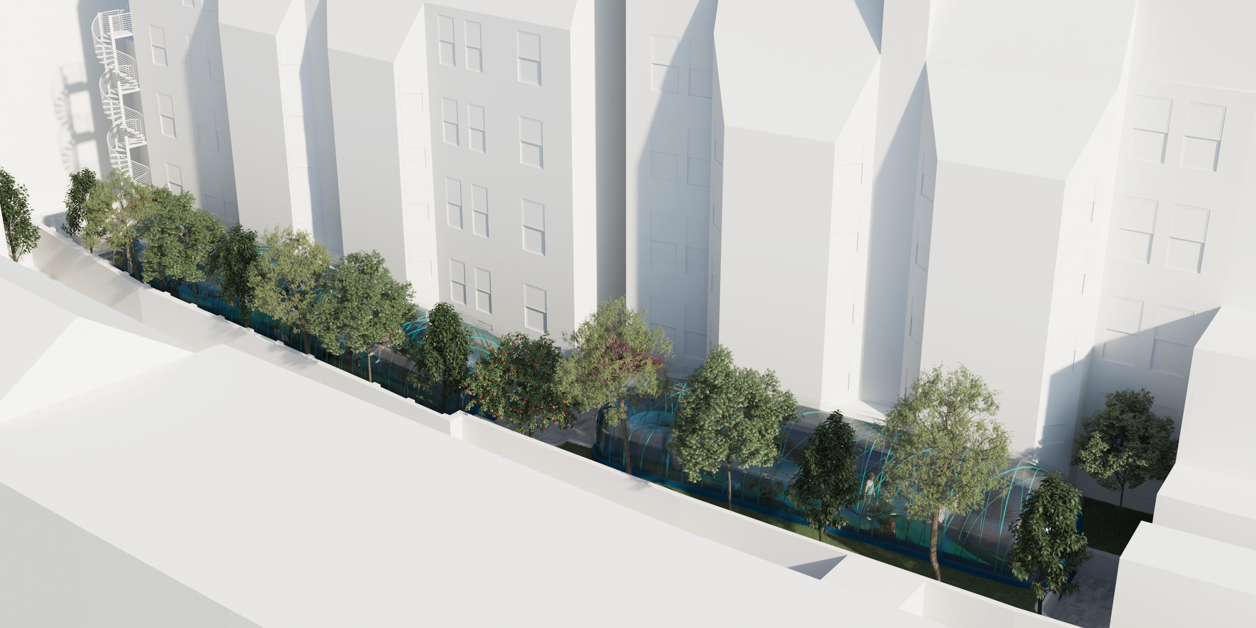
Brief description of the Pneumatic Enclosure
A pneumatic structure is any structure that is stabilized by a pressure difference between one and other side of a membrane. Without this pressure difference the structure collapses due to the fact that the membrane is only able to support tension. (Tensile Structures, Frei Otto, p. 10. 1976; Pneumatic Structures, Thomas Herzog, p. 8. 1976).
Air-supported structures, which are typical structures used to cover sport facilities like swimming pools, tennis courts or football fields, are stabilized by a pressure difference that achieves large spans with very low quantities of material due to the fact that the structure is active and counteracts the action of gravity with pressure.
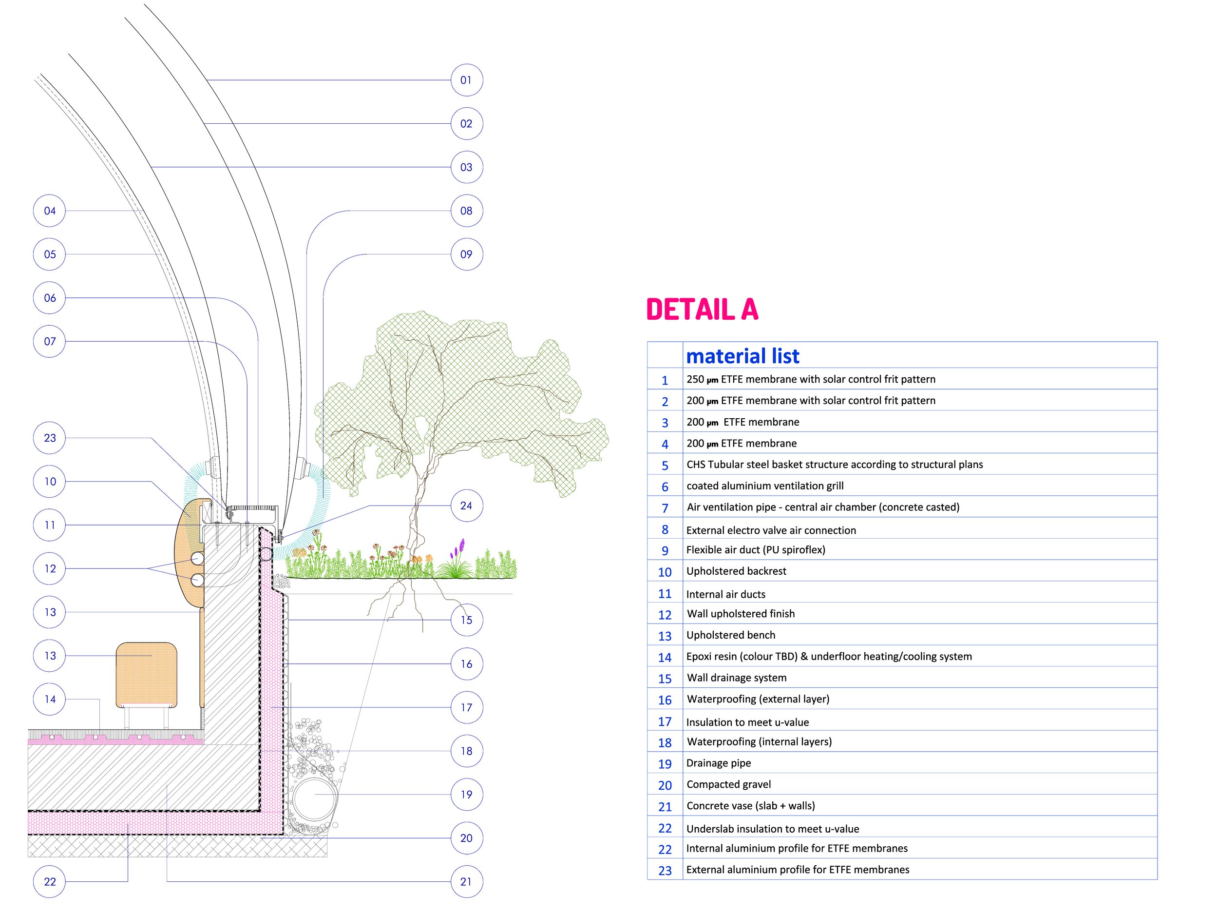
Air-supported structures usually need to have airlocks to enter and exit the main space. However, in our proposal, out of the four membranes, only the three outer membranes are air supported (M2, M3 & M4), and the internal membrane (M1) is pressed against a steel basket structure that holds membrane M1 in place.
The main benefit of this solution is that we can achieve the structural optimization of air supported structures without the need to pressurize the inhabited space. This allows natural ventilation of the space and freedom of use without the need to create air-lock entrances that limit the versatility of the space.
ETFE in building applications
Ethylene tetrafluoroethylene (ETFE) is a lightweight material with extraordinary tensile and UV resistance properties that is becoming a mainstream material for building solutions, mainly to create the enclosures of buildings in the form of roofs and facades with pressurized pillows made out of foil membranes of this material.
The increase in use of ETFE in building systems is linked to its lightweight properties and light transmittance that have a positive impact in the overall energy savings of the building process, from manufacturing of components, building and assembly processes and building use and maintenance.
Elements of the structure:
Concrete vase: The structures are partially buried to provide a low-profile and improve the thermal performance of the structures. To achieve this, we propose the creation of a concrete slab and concrete walls surrounding the perimeter in contact with the garden soil.
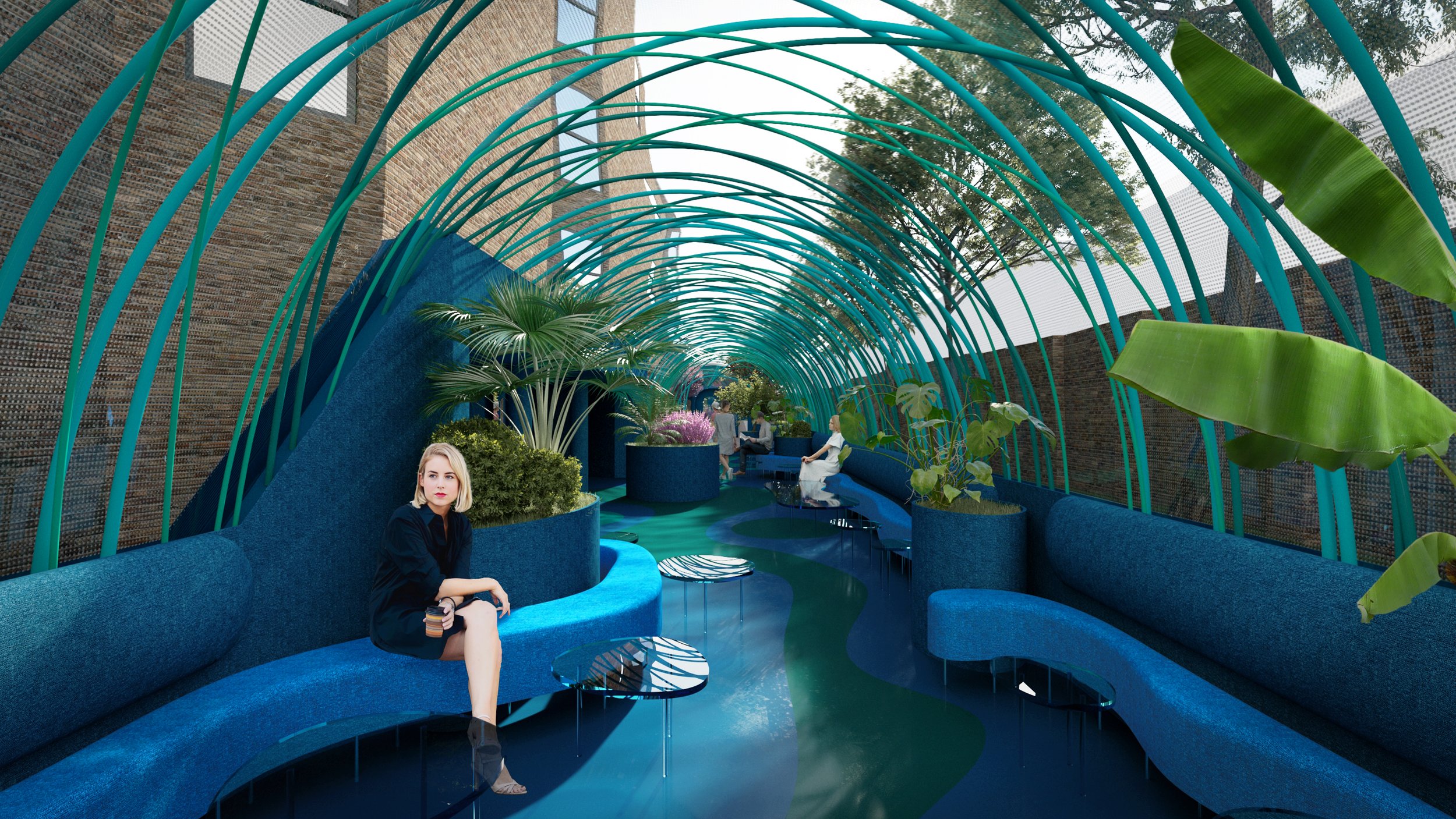
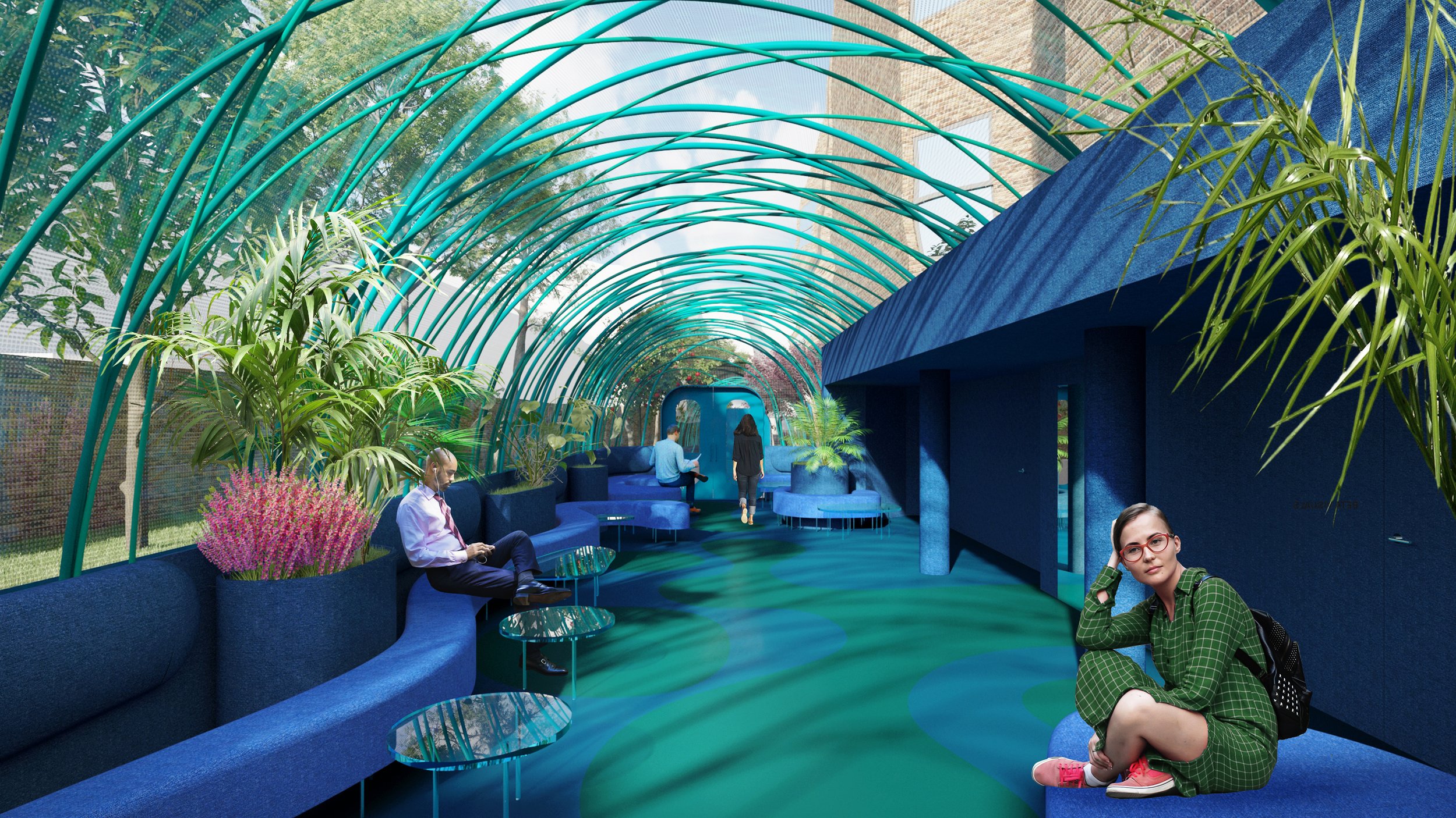
Steel nest: In order to keep the inner ETFE membrane in place we propose a steel nest formed by an array of arched steel tubes fixed to the upper edge of the concrete walls.
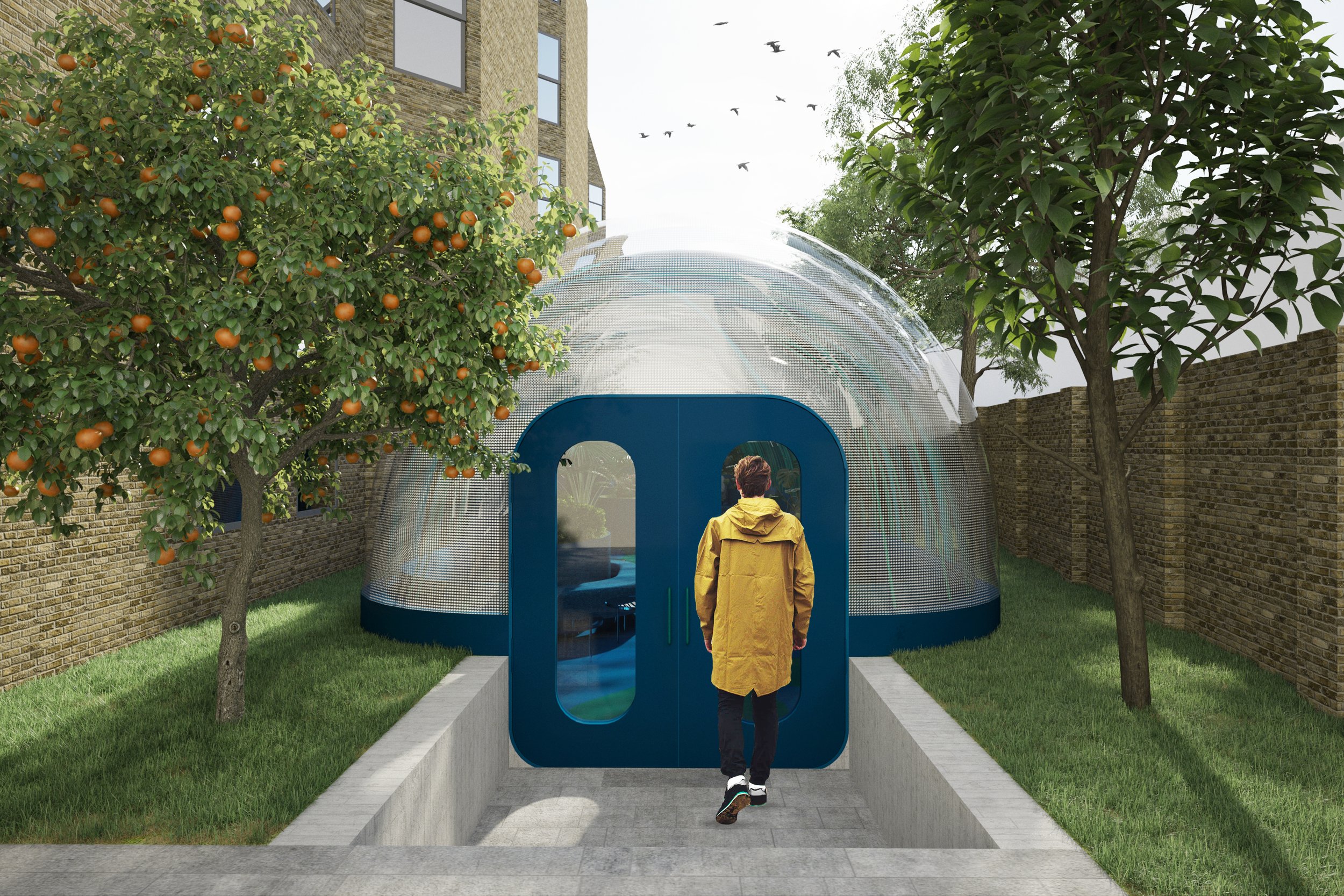
ETFE Pneumatic enclosure: The structures are covered by an air supported ETFE covering formed by four ETFE membranes.
Comparison with conventional conservatories
ETFE is:
a. LIGHTER: ETFE is a lightweight material. This implies that it needs less supporting structure. In this particular case the three outer membranes of the ETFE enclosure are air supported, which means that only the inner membrane has a steel structure to maintain its position and shape.
b. FLEXIBLE: ETFE allows the creation of custom shapes and geometries that are unfeasible to produce with glass. The double curvature geometry of the current proposal would be extremely expensive to produce with glass, which would need to be thermo moulded to achieve the required geometry. This would not only imply and increase in cost of production and installation, but would also have an embodied energy that would be unsustainable in comparison with the ETFE solution.
c. SELF-CLEANING: the surface of ETFE is smooth and allows the rain to wash away most of the dirt on the surface. Traditional external cleaning is done once every two or three years, reducing the maintenance requirements of the surface in comparison to glass.
d. ENVIRONMENTALLY FRIENDLY: ETFE is recyclable, its raw material is a class II substance admitted under the Montreal treaty, no solvents are used in the production of ETFE as it is a water based process, welding of the foils is a low energy production process, and has an estimated life of over 50 years. Lightweight properties and the possibility to roll the membranes also provides a more efficient transport to site, reducing the overall CO2 emissions of the building process.
Energy and Sustainability
a. THERMAL PERFORMANCE: the ETFE enclosure of the conservatory structures will be created by four membranes, two internal membranes (M1 & M2) and two external ones (M3 & M4), having three air chambers that will insulate the interior space from the exterior. The estimated u-value is of approximately 1,4 W/m2K.
b. LIGHT TRANSMITTANCE: ETFE is an extremely transparent material. Nevertheless, the amount of UV transmission can be tailored to the specific requirements of the project by printing patterns (called fritt) on the surface of the membranes to achieve the required g-value. The correct radiation strategy will allow the use of passive solar heating during the winter while avoiding overheating during the hot periods of the year. Using differential pressure, the light transmittance of the ETFE enclosure can vary depending on the environmental conditions.
PLANS & DIAGRAMS:
IMAGES:
PRIORY PARK ROAD CONSERVATORY STRUCTURES CREDITS:
Typology: Hotel (Common Areas)
Building Area: 185 sq m.
Authors: Isabel Collado & Ignacio Peydro
Team: Luis Francisco Núñez, Irache Portillo, Laura Rodríguez.


